WPX S1 and S1 PRO

Real charging.A clearer picture.

A Qi Sniffer for real phone charging. Observe power and Qi ASK / FSK communication, and connect the details of each wireless exchange.1

Find your S1 WPX S1 Manual
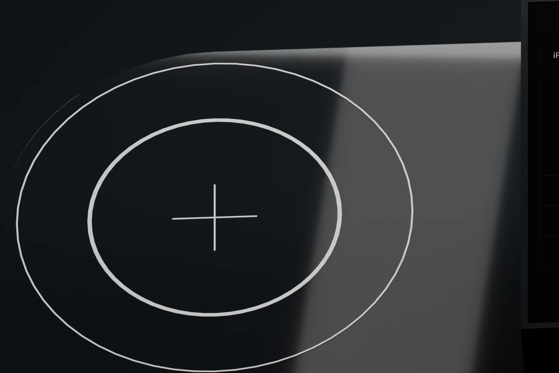
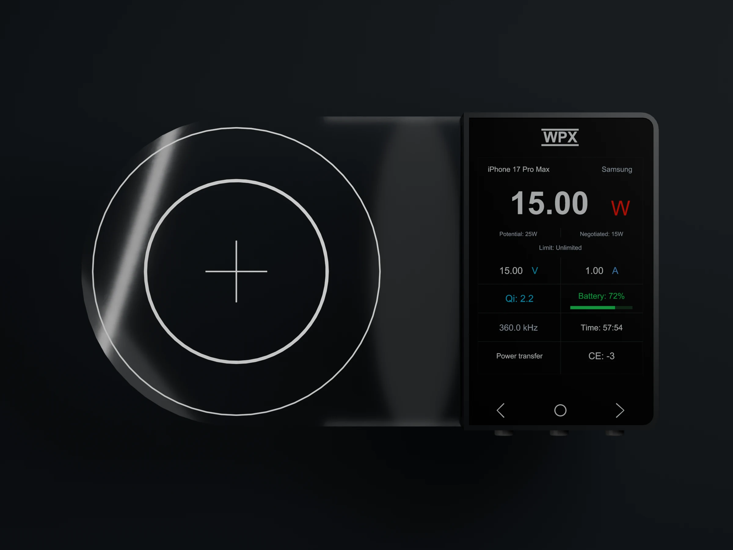
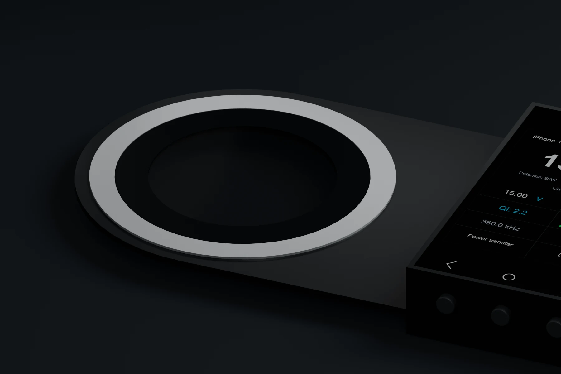
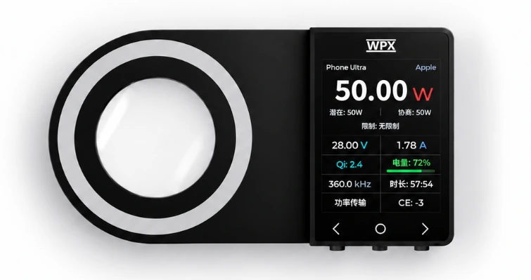
Front view of WPX S1, with the circular sensing area on the left and display unit on the right
Wireless charging analyzer. Product view and screen values are illustrative.
Observe
Real phone
Capture rate
12 MSPS
Communication
ASK / FSK
S1 PRO sensor
≈ 0.11 mm

BPP · EPP · MPP / Qi2 / Qi2.2 · Some proprietary protocolsRecognition depends on the devices and current firmware.

What makes S1 different

Real conditions.
Useful clues.

Keep the real phone in the test

Let the phone negotiate.
Let the phone charge.

Rather than replacing the phone with a receiver fixture, observe its exchange with the transmitter. Compare charging behavior across phones, charging pads and adapter combinations.

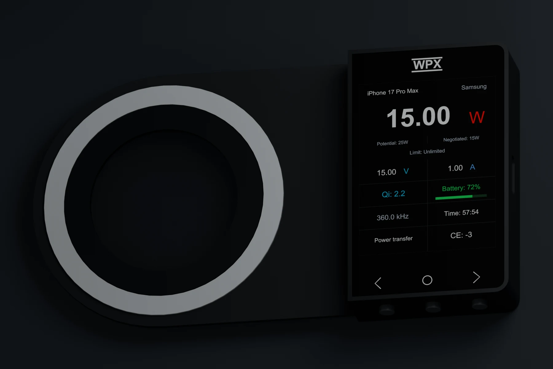
Integrated WPX S1 sensing area and display unit
An integrated sensing area and display unit for straightforward setup.

Low-disturbance capture

Observe the exchange.
Don't take it over.

The low-inductance sensing coil does not inject or modify communication data. A thin structure reduces the added gap, keeping the test closer to the original charging conditions.

Close-up of the transparent flexible S1 PRO sensing film
S1 PRO: an approximately 0.11 mm sensing area.

Connect power with communication

More than a single number.

What can the transmitter negotiate? Which mode is active? How is the current reading changing? Read power alongside protocol information for a better-informed view.

POT NEG W

Observe while charging

The phone stays.
The picture expands.

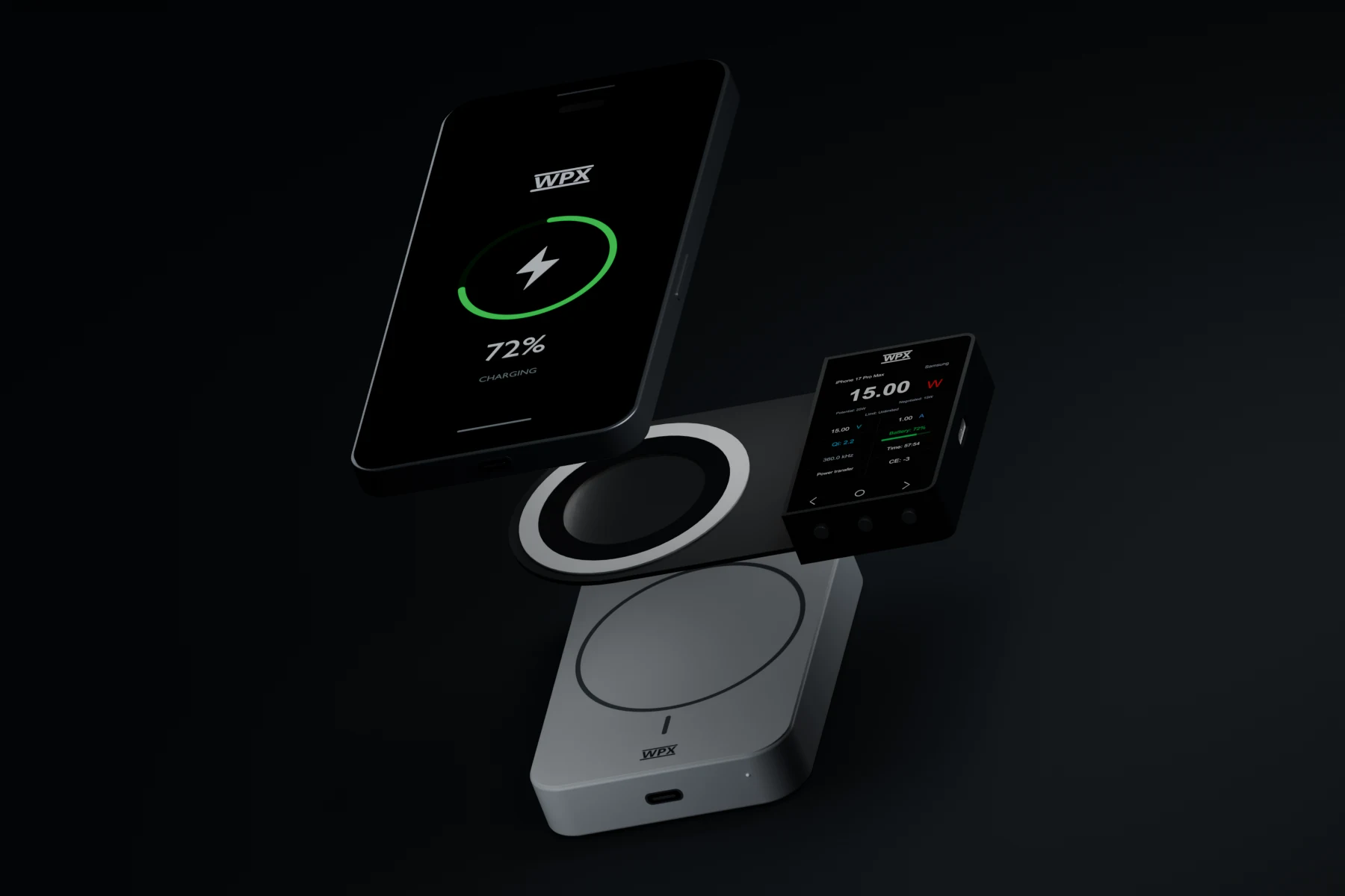
Place S1 between transmitter and phone, with the display unit to the side. USB-C power lets you check status independently; connect a computer to explore the communication in detail.

Exploded placement illustration showing phone, S1 and wireless charger
Placement illustration. Shown spacing is not an operating-distance specification.
  1. 01 / POWER

    Connect USB-C.

    Use a stable 5 V / 1 A USB supply. For desktop analysis, connect to the computer with a data-capable cable.

  2. 02 / ALIGN

    TX, S1 and phone. Aligned.

    Keep all three charging centers aligned and the stack stable. Avoid thick phone cases and metal objects that could affect the test.

  3. 03 / OBSERVE

    Follow negotiation into charging.

    Wait for charging to begin, then consider the identified protocol, negotiation information and changing power readings together.

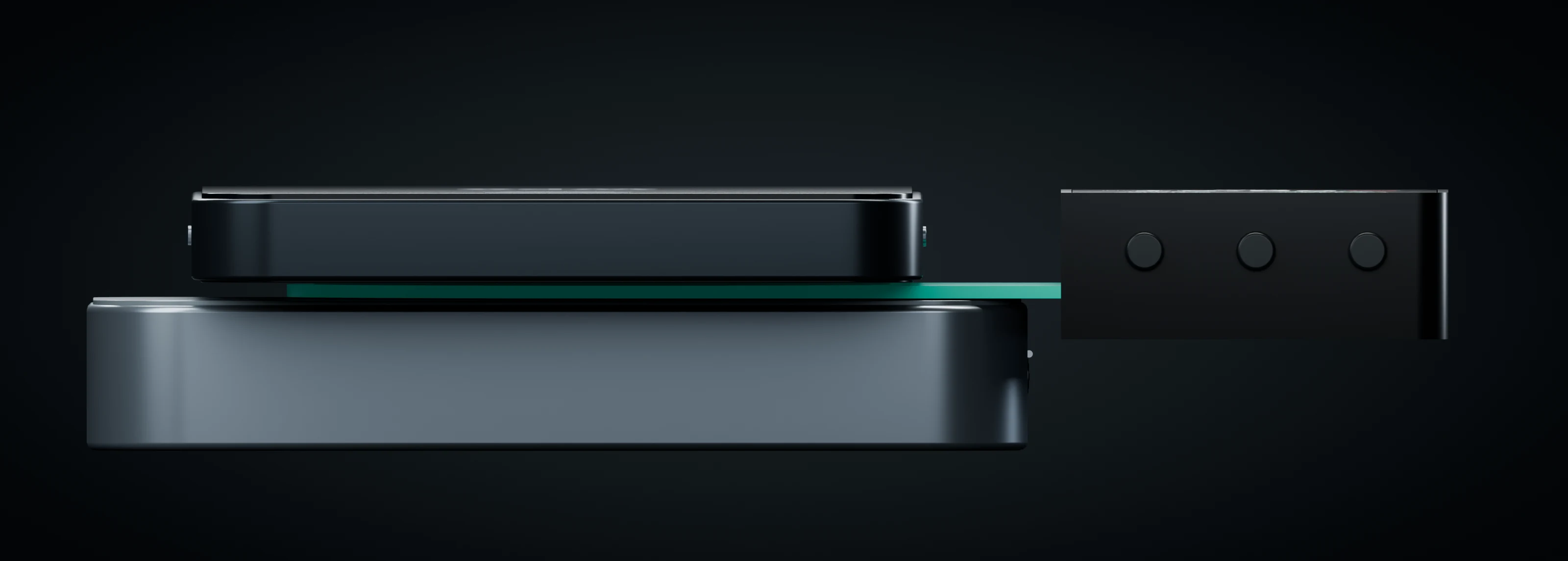
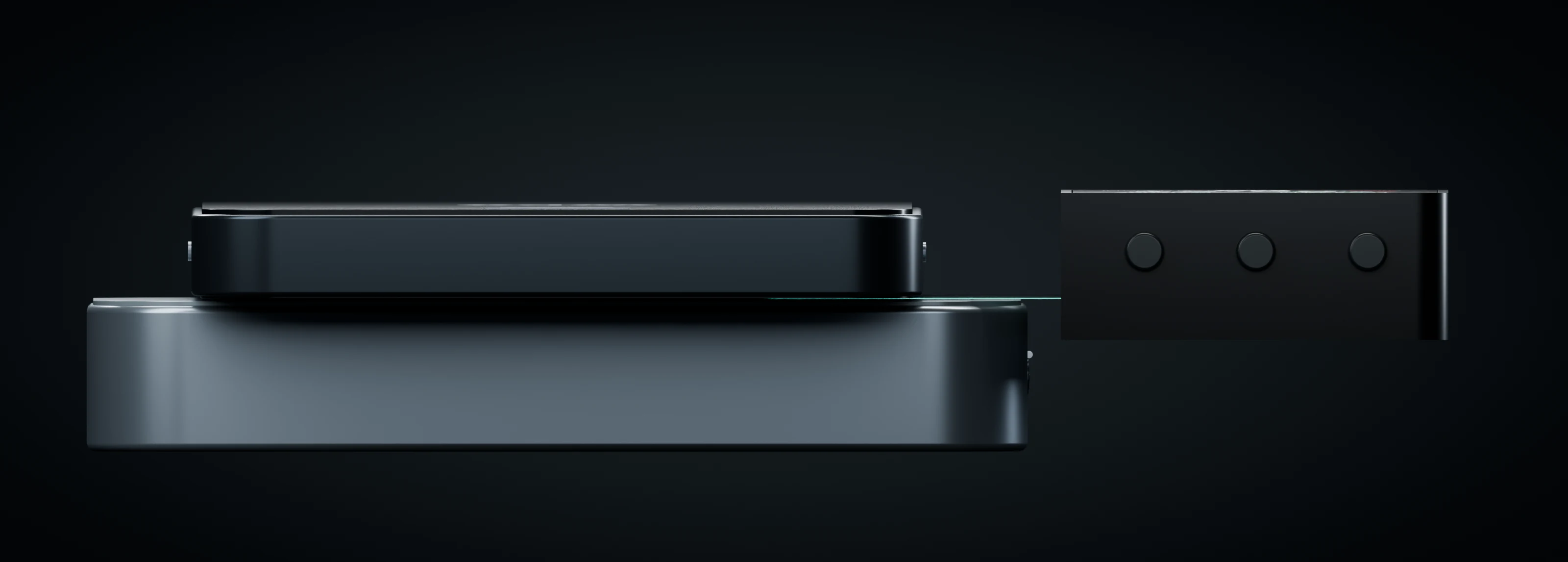
Side-view illustration of S1 between a phone and wireless transmitter
Phone above, transmitter below, sensing area between them and display unit at the side.

Different power values. Different meanings.

What it can do.
What it's doing now.

Transmitter capability, negotiation and current power are different things. S1 brings them together to help you understand whether charging has reached the expected state.

Potential power

POT

The highest negotiable power capability declared by the transmitter. It describes capability, not the power being delivered at this moment.

Negotiation information

NEG

Follow power negotiation during the handshake. The agreed contract power is available on the LINK page and must not be confused with current power.

Current received power

W

Current power derived from protocol data and device algorithms. Watching it change over time is more informative than reading a protocol name alone.

Seeing Qi2.2 does not mean the phone is currently charging at 25 W.

1. About the data: Phone power, voltage, current, battery level and device information primarily come from wireless charging protocol analysis and device algorithms. Available fields and recognition depend on the protocol, phone software, transmitter implementation and firmware. Some fields may be absent or decoded incorrectly. Consider negotiation, current readings and charging conditions together, rather than inferring power from a protocol version alone. Read the full manual.
Thin by design

A thinner layer.
A closer look.

S1 PRO · Transparent flexible FPC0.11 mm

Approximately 0.11 mm at the sensing area, excluding the display unit.

A thinner sensor means a smaller added gap. S1 PRO offers another option when the effect of inserting a test device matters to your analysis.

S1's approximately 1.1 mm magnetic structure puts straightforward, repeatable alignment first.

Transparent S1 PRO sensing area and side-mounted display
The transparent sensing film and bridge make the thin structure visible.
Close-up of the S1 magnetic alignment ring and transparent center window
S1. Straightforward alignment.A magnetic ring and transparent center window support setup and positioning.
S1 PRO flexible transparent FPC sensing rings and connection bridge
S1 PRO. A smaller gap.Transparent flexible FPC for an ultra-thin sensing structure.
See S1 PRO's thin structure from the side.
Side view of the S1 PRO sensing area between phone and charger
Installation illustration. Sensing-area thickness is distinct from display-unit thickness.

Dual FPGA architecture

Speed, with
detail in mind.

High-speed signal capture

12MSPS

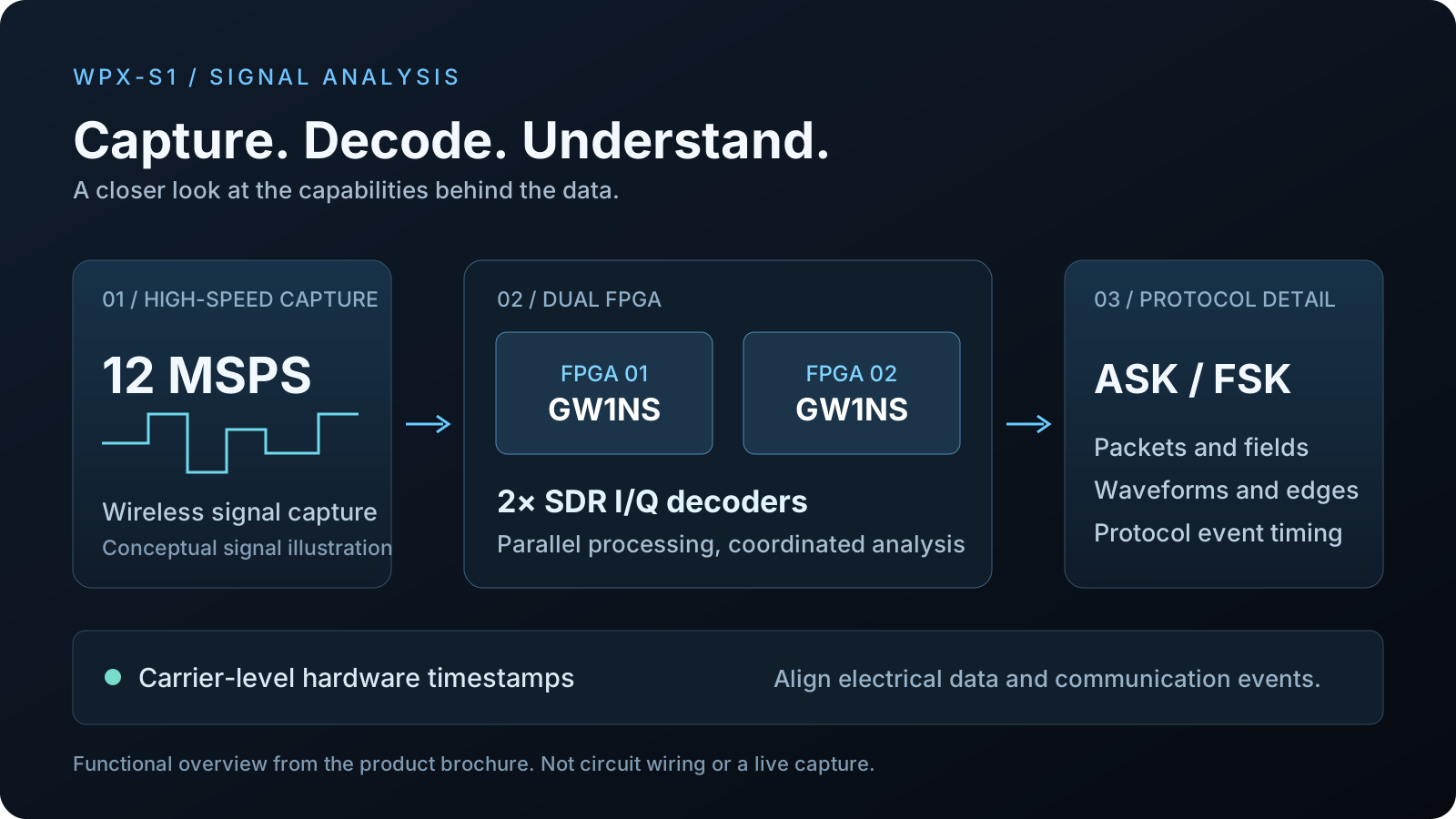
12 MSPS capture, SDR I/Q decoding and hardware timestamps turn wireless exchanges into waveforms, edges and timing you can inspect.

Coordinated FPGAs
2× GW1NSCapture and protocol analysis
SDR I/Q decoders
Parallel signal processing
Communication
ASK / FSKConnect both sides of the exchange
Hardware timestamps
Carrier-levelInspect the order of key events
Explore capture, decoding and protocol analysis.
Functional overview of 12 MSPS capture, two GW1NS FPGAs and ASK FSK analysis
Functional illustration, not circuit wiring or a measured waveform.

Qi protocol analysis

When something goes wrong,
follow the exchange.

From ASK / FSK packets to decoded fields, waveform navigation and time cursors. Move from “how is it charging?” to “what happened along the way?”

01 / HANDSHAKE & NEGOTIATION

Where did fast charging stall?

Inspect communication direction, packets and fields in time order. Follow identification, configuration, negotiation and power transfer.

02 / INTERRUPTIONS & ANOMALIES

What happened before it stopped?

Use the charging phase, recent EPT information and waveform timing to review key events around an interruption and investigate compatibility.

03 / REPRODUCE & REVIEW

Keep the issue with its evidence.

Filter packets, zoom into events and measure timing with cursors. Save the complete session for later reproduction and review.

The phone. The transmitter. This connection.

RX · Receiver

Read receiver identity and declared capabilities to investigate phone and compatibility differences.

QI VERSION / PRMC / BASIC ID / RX CAPS

TX · Transmitter

Inspect transmitter capability, the currently negotiable limit and reported reasons for power limits.

POTENTIAL / NEGOTIABLE / PTMC / LIMIT

LINK · Connection

Check the mode, charging phase, agreed power contract and most recently observed EPT reason.

MODE / PHASE / CONTRACT / LAST EPT

Device identity depends on protocol data and the database. Declared authentication capability does not prove successful authentication; an unobserved foreign-object or EPT report does not rule out every fault.

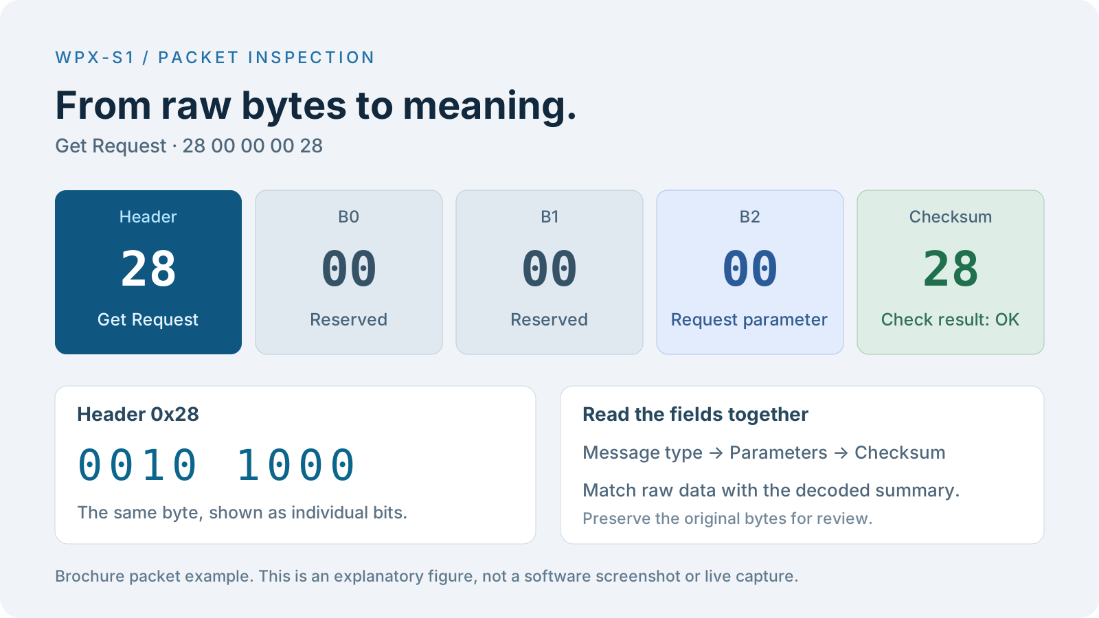
See how a Get Request packet is broken down.
Header, parameter and checksum fields in the Get Request example 28 00 00 00 28
A static packet example from the brochure, explaining how raw bytes map to fields.

One device. Two desktop perspectives.

Status on site.
The bigger picture on your desktop.

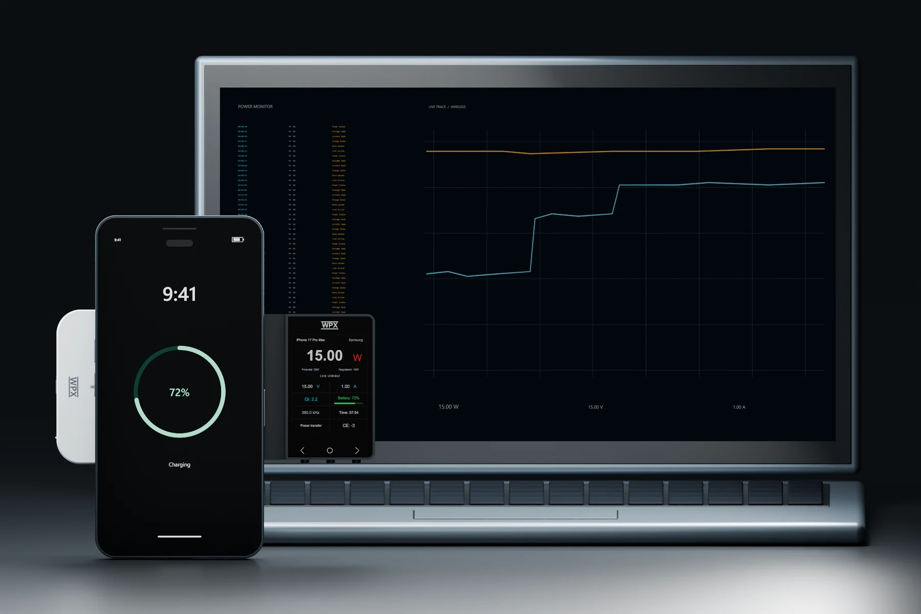
Use the device display for a quick view of charging status. Connect WPX software and choose normal or professional mode for the depth of analysis you need.

Illustrated desktop workflow for wireless charging analysis with S1
Desktop workflow illustration. The computer display is not an actual software screenshot.

Normal mode · Everyday testing

Wireless Charging Tester

View received power, rectified voltage and current, battery level, protocol, frequency and charging phase. Follow stability and changing parameters on curves.

Curve data CSV import / export

Professional mode · Communication analysis

Qi Protocol Analyzer

Inspect ASK / FSK packets, raw waveforms, decoded fields and protocol timing, with packet filtering, event navigation and time measurement.

Complete test session saving

USB-C data connection · Windows 10 (64-bit) or later · Runs without installation after download; refer to the software release notes.

Download softwareWPX S1 Manual

AI MCP

Start with the records.
Build an analysis.

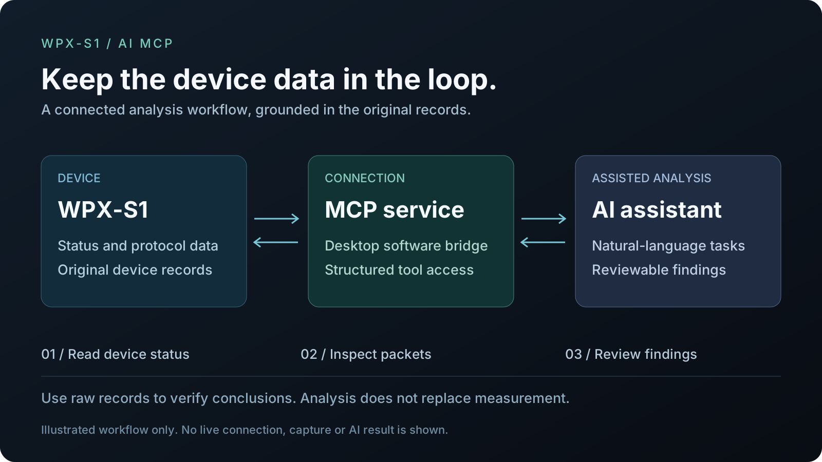
Connect the device and an AI assistant through an MCP service. Use natural language to read status, assist with protocol review and explore scripts and automation workflows.

Explore AI MCP
An example analysis request
Read device status, then group recent valid packets by ASK / FSK. Look for repeated messages, checksum anomalies and event order.

This is a task example. Verify AI analysis against the original data; it does not replace measurement or engineering judgment.

See how the device and AI assistant connect.
Functional diagram connecting S1 to an AI assistant through desktop software and MCP
A connection workflow illustration, not a live capture or generated analysis result.

Interactive 3D view

Change the angle.
See the details.

Open a full-screen model explorer to rotate, zoom and pan each device before choosing the right S1 for your test.

WPX S1 3D model previewS1

Magnetic alignment · Direct setup

WPX S1

Rotate the device to inspect the display unit, sensing area and magnetic positioning structure.

Open S1 viewer
WPX S1 PRO 3D model previewS1 PRO

Flexible FPC · Smaller added gap

WPX S1 PRO

Explore the transparent flexible FPC and side unit when insertion impact matters most.

Open S1 PRO viewer

Choose your S1

Which one fits
your next test?

The key choice: straightforward magnetic positioning or a smaller added gap.

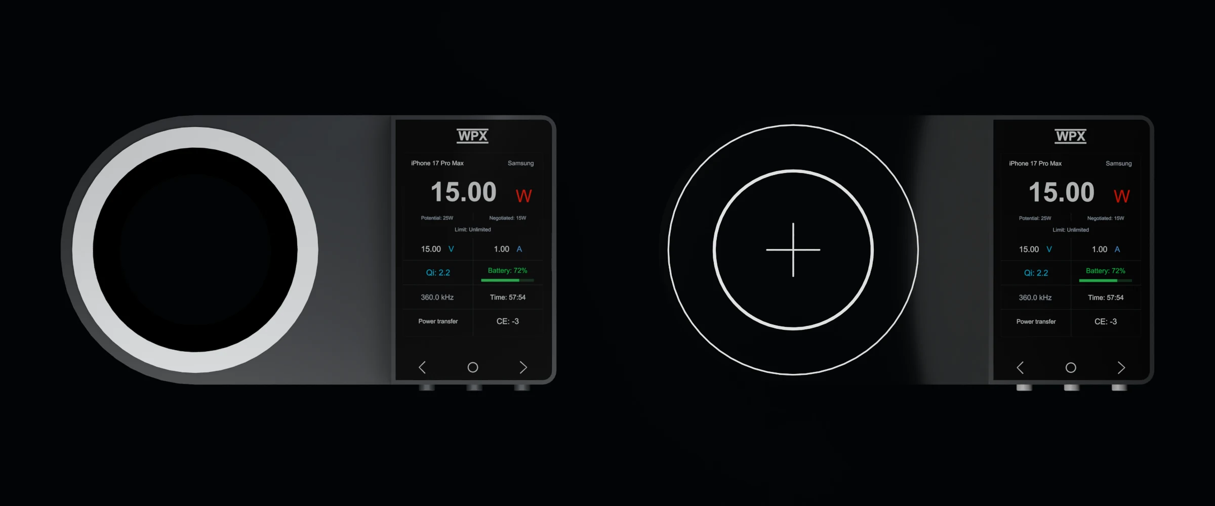
Standard S1 on the left and S1 PRO on the right, front-facing and horizontal at the same scale
Left: S1 magnetic sensing assembly. Right: S1 PRO transparent flexible FPC.

Magnetic alignment. Straightforward setup.

WPX S1

1.1 mm

Approximately 1.1 mm sensing area

For everyday debugging, quick positioning and comparisons across different phone and transmitter combinations.

Designed for a smaller added gap.

WPX S1 PRO

0.11 mm

Approximately 0.11 mm flexible FPC sensing area

For analysis where the charging gap and the effect of inserting a test device deserve closer attention.

Two sensing structures. The key differences.
SpecificationS1S1 PRO
Sensing-area thicknessApprox. 1.1 mmApprox. 0.11 mm
Sensing designMagnetic alignmentUltra-thin flexible FPC
Charging efficiency impact≤1%≤0.2%
MatedQ change≤2.3%≤0.27%
K-value change≤3%≤0.1%

Structural and performance data are from the product brochure. Thickness excludes the display unit; efficiency impact and change rates are not measurement-accuracy specifications. Recognition supports Qi BPP, EPP, MPP / Qi2 / Qi2.2 and some proprietary protocols, subject to current firmware and the devices used.

Explore purchasing optionsNeed receiver simulation and load testing? Explore WPX-01A

A few more things worth knowing.

Why is power low even when a fast-charging protocol is shown?

Battery level, temperature, phone software, the adapter and transmitter capability all affect power. Consider negotiation and changing current readings together; a Qi version alone does not establish a particular charging power.

Why are a phone model or battery level sometimes missing?

These fields depend on the device's protocol messages, the recognition database and current firmware. Missing or unsupported fields may not appear. Their absence does not by itself mean the phone is not charging normally.

Do I always need a computer?

You can view charging status on the device without a computer, but S1 still requires USB-C power. Connect a data-capable cable and desktop software when you need detailed packets, communication waveforms and protocol timing.

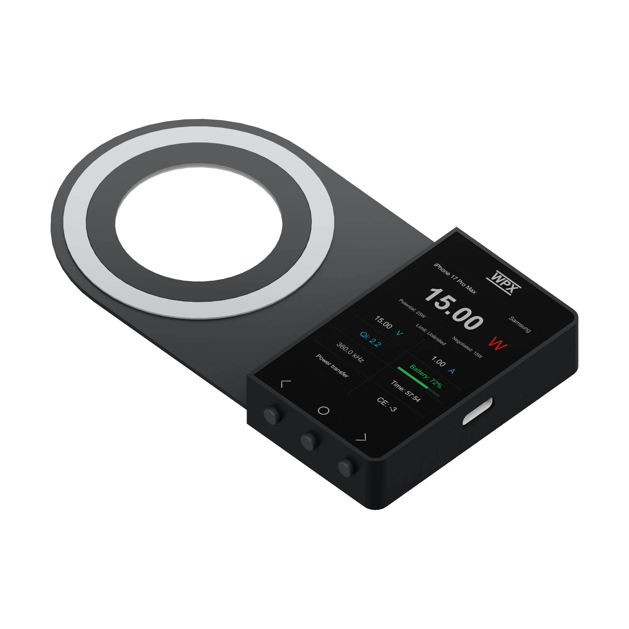
Angled view of the WPX S1 device
S1 shown. The supplied device depends on the model purchased.

In the box

Ready to start observing.

  • WPX S1 series deviceYour selected model
  • USB data cableFor power and computer data connection

Package contents depend on the model purchased.

Product and usage images are rendered illustrations; displays and charts do not represent live measurements. Phones, chargers and computers are scene accessories, not included in the device package. Illustrated spacing is not an operating-distance specification. Features, available fields and export options depend on current firmware and software.